4 Wire O2 Sensor Wiring
4 Wire O2 Sensor Wiring - The oxygen sensor signal wires are responsible for transmitting the voltage signal produced by the sensor to the engine control module (ecm). However, the concept is the same for 1, 2, and 3 wire universal sensors. Oxygen sensors record an exhaust’s o2 quantity and send it to the vehicle’s electronic control unit (ecu). If the color of your original wires. I have a 89 ford bronco ii project car with a 2.9 fuel injected engine. Web unlock the secrets of o2 sensors with our comprehensive guide!
The oxygen sensor i took out was a 4 wire the one that i was sold was a 3 wire, when asked about the difference i was told all of them are now 3 wire. Two white wires, one black wire, and one gray wire. Each wire has a specific function that must be properly connected to ensure accurate readings and efficient engine performance. The signal wire, power wire, ground wire, and heater wire. Web 89ford bronco ii oxygen sensor 4 or 3 wire.
Identify the sensor’s four wires: Web 89ford bronco ii oxygen sensor 4 or 3 wire. Web have you ever wondered what the wire colors represent in your ntk oxygen sensors? Web how to tell which o2 sensor is bad + 4 wire o2 sensor wiring diagram. 🚗💡 dive into 'mastering o2 sensors:
Denso O2 Sensor Pinout Sensor Education Blog

However, the concept is the same for 1, 2, and 3 wire universal sensors. I have a 89 ford bronco ii project car with a 2.9 fuel injected engine. Web the wiring diagram for a 4 wire oxygen sensor includes four wires: I just put a clutch in it and replaced the y pipe along with the oxygen sensor. Web.
Understanding 4 Wire O2 Sensor Wiring Harness Diagram Moo Wiring

However, the concept is the same for 1, 2, and 3 wire universal sensors. Ensuring a secure and durable connection is essential to maintain accurate readings and optimal engine performance. Identify the sensor’s four wires: If the color of your original wires. The signal wire is responsible for transmitting the oxygen measurement data to the ecu, allowing it to make.
Toyota 4 Wire O2 Sensor Wiring Diagram Esquilo.io
Learn about wire connections, color codes, and troubleshooting tips for optimal engine performance. I just put a clutch in it and replaced the y pipe along with the oxygen sensor. The signal wire is responsible for transmitting the oxygen measurement data to the ecu, allowing it to make necessary adjustments. Oxygen sensors record an exhaust’s o2 quantity and send it.
[DIAGRAM] 4 Wire O2 Sensor Wiring Diagram Toyota
![[DIAGRAM] 4 Wire O2 Sensor Wiring Diagram Toyota](https://i2.wp.com/forum.ih8mud.com/attachments/img_0354-large-jpg.384171/)
I need to know whick wire is the feed back and which ones are for the heated portion of it. To test, set the multimeter to resistance mode and use it to probe and figure out which wires register a. Web unlock the secrets of o2 sensors with our comprehensive guide! This guide explains components, reading diagrams, importance of proper.
Understanding 4 Wire O2 Sensor Wiring Diagram Basics Wiring Diagram

Web universal oxygen (o2) sensors. I need to know whick wire is the feed back and which ones are for the heated portion of it. Identify the sensor’s four wires: Learn about wire connections, color codes, and troubleshooting tips for optimal engine performance. Web this should be done first.
Chevy O2 Sensor Wiring Diagram

You can solder the wires, or use connector pieces if they’re provided with the replacement set. I just put a clutch in it and replaced the y pipe along with the oxygen sensor. Web this should be done first. Identify the sensor’s four wires: Web how to tell which o2 sensor is bad + 4 wire o2 sensor wiring diagram.
Toyota 4 Wire O2 Sensor Wiring Diagram Pictures

Received 0 likes on 0 posts. Web have you ever wondered what the wire colors represent in your ntk oxygen sensors? I just put a clutch in it and replaced the y pipe along with the oxygen sensor. If the color of your original wires. The signal wire, power wire, ground wire, and heater wire.
42 4 wire o2 sensor wiring diagram

The oxygen sensor signal wires are responsible for transmitting the voltage signal produced by the sensor to the engine control module (ecm). Two white wires, one black wire, and one gray wire. The signal wire, power wire, ground wire, and heater wire. 🚗💡 dive into 'mastering o2 sensors: To test, set the multimeter to resistance mode and use it to.
toyota oxygen sensor wiring colors Wiring Diagram and Schematic Role

Two white wires, one black wire, and one gray wire. I just put a clutch in it and replaced the y pipe along with the oxygen sensor. Web about press copyright contact us creators advertise developers terms privacy policy & safety how youtube works test new features nfl sunday ticket press copyright. You can solder the wires, or use connector.
4 Wire Oxygen Sensor Diagram

In case your mileage is going bad, this simply means your fuel trims are putting in lots of gas and haven’t been updated in a while. Web 89ford bronco ii oxygen sensor 4 or 3 wire. You can solder the wires, or use connector pieces if they’re provided with the replacement set. Web about press copyright contact us creators advertise.
4 Wire O2 Sensor Wiring - Web about press copyright contact us creators advertise developers terms privacy policy & safety how youtube works test new features nfl sunday ticket press copyright. Oxygen sensors record an exhaust’s o2 quantity and send it to the vehicle’s electronic control unit (ecu). Received 0 likes on 0 posts. Web have you ever wondered what the wire colors represent in your ntk oxygen sensors? Knowing which of the upstream or downstream oxygen sensors is going bad is the same as understanding which o2 sensor is bad. Ensuring a secure and durable connection is essential to maintain accurate readings and optimal engine performance. Premium universal oxygen sensors with oe smartlink are quick and easy to install. This guide explains components, reading diagrams, importance of proper wiring, and considerations. I need to know whick wire is the feed back and which ones are for the heated portion of it. Identify the sensor’s four wires:
Web how to tell which o2 sensor is bad + 4 wire o2 sensor wiring diagram. Each wire has a specific function that must be properly connected to ensure accurate readings and efficient engine performance. Web unlock the secrets of o2 sensors with our comprehensive guide! I have a 89 ford bronco ii project car with a 2.9 fuel injected engine. Web about press copyright contact us creators advertise developers terms privacy policy & safety how youtube works test new features nfl sunday ticket press copyright.
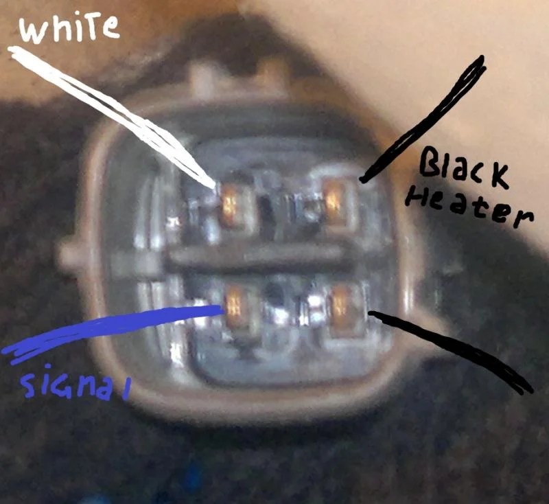
Web have you ever wondered what the wire colors represent in your ntk oxygen sensors? Web about press copyright contact us creators advertise developers terms privacy policy & safety how youtube works test new features nfl sunday ticket press copyright. Web the o2 sensor has 2 white wires and a black wire, the other side of the connection has black wire a gray with yelow stripe and a green withe a purple stripe. Web universal oxygen (o2) sensors.
Web about press copyright contact us creators advertise developers terms privacy policy & safety how youtube works test new features nfl sunday ticket press copyright. You can solder the wires, or use connector pieces if they’re provided with the replacement set. Two for the oxygen sensor signal and two for the sensor’s heater circuit.
Web the wiring diagram for a 4 wire oxygen sensor includes four wires: Web about press copyright contact us creators advertise developers terms privacy policy & safety how youtube works test new features nfl sunday ticket press copyright. Web how to tell which o2 sensor is bad + 4 wire o2 sensor wiring diagram.
Each Wire Has A Specific Function That Must Be Properly Connected To Ensure Accurate Readings And Efficient Engine Performance.
I need to know whick wire is the feed back and which ones are for the heated portion of it. This guide explains components, reading diagrams, importance of proper wiring, and considerations. Web about press copyright contact us creators advertise developers terms privacy policy & safety how youtube works test new features nfl sunday ticket press copyright. Two white wires, one black wire, and one gray wire.
Web This Video Briefly Explains How To Install A Universal 4 Wire Oxygen Sensors.
Web the wiring diagram for a 4 wire oxygen sensor includes four wires: Web this should be done first. If the color of your original wires. Web have you ever wondered what the wire colors represent in your ntk oxygen sensors?
Received 0 Likes On 0 Posts.
The oxygen sensor signal wires are responsible for transmitting the voltage signal produced by the sensor to the engine control module (ecm). Web universal oxygen (o2) sensors. 🚗💡 dive into 'mastering o2 sensors: I just put a clutch in it and replaced the y pipe along with the oxygen sensor.
Learn About Wire Connections, Color Codes, And Troubleshooting Tips For Optimal Engine Performance.
Premium universal oxygen sensors with oe smartlink are quick and easy to install. However, the concept is the same for 1, 2, and 3 wire universal sensors. Connect one of the white wires to the sensor’s signal output pin on the ecu. To test, set the multimeter to resistance mode and use it to probe and figure out which wires register a.