Bosch 4 Wire O2 Sensor Wiring Diagram
Bosch 4 Wire O2 Sensor Wiring Diagram - Web i was sent a bosch universal o2 downstream sensor however their wiring diagram does not match that of the original sensor lead which i need to chop onto. 6066 is an lsu 4.0 sensor. Web 5 wire oxygen sensor working principle, construction and wiring explained in detail with animation. Originally, automotive oxygen sensors had only one or two wires and were made from zirconia in a thimble shape. Web understanding the wiring diagram of your bosch oxygen sensor is essential for proper installation and troubleshooting. A signal wire, a ground wire, a heater wire, and a reference wire.
The bosch oxygen sensor wiring diagram typically consists of four wires: Web the wiring diagrams for oxygen sensors vary based on the make, model, and year of the vehicle. Web this video briefly explains how to install a universal 4 wire oxygen sensors. Web the wiring diagram for a bosch 5 wire o2 sensor typically includes five wires: This should be done first.
They come with about 2ft of wiring, which ended up working perfectly. Web the wiring diagrams for oxygen sensors vary based on the make, model, and year of the vehicle. The bosch oxygen sensor wiring diagram typically consists of four wires: Web i purchased a set of bosch #15738 universal o2 sensors to replace the oe ones. Originally, automotive oxygen sensors had only one or two wires and were made from zirconia in a thimble shape.
bosch 4 wire o2 sensor wiring diagram RihaniNurlita

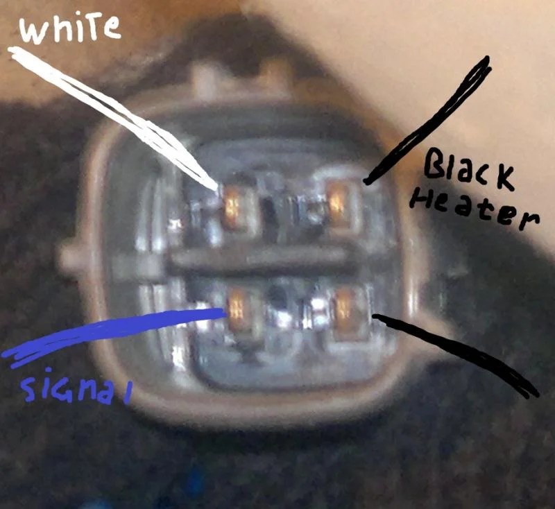
Web currently bosch offers 12 different 4 wire sensors and 2 different 3 wire sensors to provide the closest match to oem sensor performance. Remove the oe sensor from vehicle. Web 5 wire oxygen sensor working principle, construction and wiring explained in detail with animation. 4 wire o2 sensor diagram Web sensor connector is shown looking at the mating face.
4 wire sensor wiring

Web i purchased a set of bosch #15738 universal o2 sensors to replace the oe ones. Fueltech wideband lambda (o2) meter slim is a tool used for monitoring and adjusting combustion engines. This equipment conditions and reads the bosch lsu 4.2 wideband lambda sensor with speed and precision. Web oxygen sensors were developed by the robert bosch company and first.
Howto Tuning Carbs with an Oxygen Sensor and A/F Gauge

Bosch number is 0 258 006 066. Note that the green pin is from the rcal part inside the sensor connector housing, and thus there's no green wire to the sensor assembly (represent by the blue area to the right). See the technical info tab for a diagram of the connector system, featuring special high. The sensor generally consists of.
bosch 4 wire o2 sensor wiring diagram RihaniNurlita

Web no, you don't have to rely on wire colors to figure out what's what. The signal wire is responsible for transmitting the oxygen measurement data to the ecu, allowing it to make necessary adjustments. They come with about 2ft of wiring, which ended up working perfectly. This should be done first. Cut the wiring of oe sensor 4 from.
Bosch 4 Wire O2 Sensor Wiring Diagram Hastalavista 4 Wire O2 Sensor

Web 5 wire oxygen sensor working principle, construction and wiring explained in detail with animation. Learn about the different wire colors and their functions to ensure proper installation and functionality of your o2 sensor. Remove the oe sensor from vehicle. Bosch number is 0 258 006 066. Web no, you don't have to rely on wire colors to figure out.
Bosch 5 Wire Wideband O2 Sensor Wiring Diagram Wiring Draw

However, the concept is the same for 1, 2, and 3 wire universal sensors. Web 5 wire oxygen sensor working principle, construction and wiring explained in detail with animation. See the technical info tab for a diagram of the connector system, featuring special high. The bosch oxygen sensor wiring diagram typically consists of four wires: The wide band lambda sensor.
Honda Oxygen Sensor Wiring Diagram A Complete Guide

You can solder the wires, or use connector pieces if they’re provided with the replacement set. Web sensor connector is shown looking at the mating face. 6066 is an lsu 4.0 sensor. Cut the wiring of oe sensor 4 from end of connector as illustrated. Web understanding the wiring diagram of your bosch oxygen sensor is essential for proper installation.
Toyota 4 Wire O2 Sensor Wiring Diagram Esquilo.io
Remove the oe sensor from vehicle. 4 wire o2 sensor diagram How 5 wire o2 sensor designed with nernst cell and pump cell combination? Web oxygen sensors were developed by the robert bosch company and first used on volvo applications in the late 1970’s. Two black wires, one white wire, and one gray wire.
[DIAGRAM] Bosch O2 Sensor Wiring Diagram 3 Wire Connector MYDIAGRAM
![[DIAGRAM] Bosch O2 Sensor Wiring Diagram 3 Wire Connector MYDIAGRAM](https://i2.wp.com/forum.ih8mud.com/attachments/img_0354-large-jpg.384171/)
Web the 6th wire heading off to the ecu is connected to a resistor inside the o2 sensor connector that is laser trimmed at the factory for calibration purposes. Cut the wiring of oe sensor 4 from end of connector as illustrated. Web when wiring the bosch universal oxygen sensor, it is important to follow the manufacturer’s instructions and refer.
Nissan Oxygen Sensor Wiring Diagram

Web 5 wire oxygen sensor working principle, construction and wiring explained in detail with animation. Remove the oe sensor from vehicle. Web i purchased a set of bosch #15738 universal o2 sensors to replace the oe ones. Web no, you don't have to rely on wire colors to figure out what's what. Web the wiring diagrams for oxygen sensors vary.
Bosch 4 Wire O2 Sensor Wiring Diagram - Remove the oe sensor from vehicle. The sensor generally consists of four wires with specific functions: The bosch oxygen sensor wiring diagram typically consists of four wires: This should be done first. A signal wire, a ground wire, a heater wire, and a reference wire. Learn about the different wire colors and their functions to ensure proper installation and functionality of your o2 sensor. Oxygen sensors can be located in a manifold or exhaust pipe. If the color of your original. Web no, you don't have to rely on wire colors to figure out what's what. Web oxygen sensors were developed by the robert bosch company and first used on volvo applications in the late 1970’s.
Web no, you don't have to rely on wire colors to figure out what's what. If the color of your original. Web currently bosch offers 12 different 4 wire sensors and 2 different 3 wire sensors to provide the closest match to oem sensor performance. Learn about the different wire colors and their functions to ensure proper installation and functionality of your o2 sensor. The signal wire is responsible for transmitting the oxygen measurement data to the ecu, allowing it to make necessary adjustments.
Fueltech wideband lambda (o2) meter slim is a tool used for monitoring and adjusting combustion engines. This should be done first. Web understanding the wiring diagram of your bosch oxygen sensor is essential for proper installation and troubleshooting. Note that the green pin is from the rcal part inside the sensor connector housing, and thus there's no green wire to the sensor assembly (represent by the blue area to the right).
Oem is white, red, grey and black. Web currently bosch offers 12 different 4 wire sensors and 2 different 3 wire sensors to provide the closest match to oem sensor performance. 4 wire o2 sensor diagram
Cut the wiring of oe sensor 4 from end of connector as illustrated. This equipment conditions and reads the bosch lsu 4.2 wideband lambda sensor with speed and precision. Note that the green pin is from the rcal part inside the sensor connector housing, and thus there's no green wire to the sensor assembly (represent by the blue area to the right).
Bosch Number Is 0 258 006 066.
Oxygen sensors can be located in a manifold or exhaust pipe. Originally, automotive oxygen sensors had only one or two wires and were made from zirconia in a thimble shape. The signal wire is responsible for transmitting the oxygen measurement data to the ecu, allowing it to make necessary adjustments. Web 5 wire oxygen sensor working principle, construction and wiring explained in detail with animation.
You Can Solder The Wires, Or Use Connector Pieces If They’re Provided With The Replacement Set.
This should be done first. Web the 6th wire heading off to the ecu is connected to a resistor inside the o2 sensor connector that is laser trimmed at the factory for calibration purposes. See the technical info tab for a diagram of the connector system, featuring special high. 4 wire o2 sensor diagram
Web When Wiring The Bosch Universal Oxygen Sensor, It Is Important To Follow The Manufacturer’s Instructions And Refer To The Wiring Diagram Provided.
Fueltech wideband lambda (o2) meter slim is a tool used for monitoring and adjusting combustion engines. However, the concept is the same for 1, 2, and 3 wire universal sensors. Web the wiring diagrams for oxygen sensors vary based on the make, model, and year of the vehicle. Two black wires, one white wire, and one gray wire.
Web Find Out How To Correctly Wire A Bosch Universal O2 Sensor With This Comprehensive Wiring Diagram.
This equipment conditions and reads the bosch lsu 4.2 wideband lambda sensor with speed and precision. This is a sample installation location. The bosch oxygen sensor wiring diagram typically consists of four wires: Web oxygen sensors were developed by the robert bosch company and first used on volvo applications in the late 1970’s.